About the project
Engineering meets art.
Places Between Lines is where our passion, ideas and skills come together to create something new.
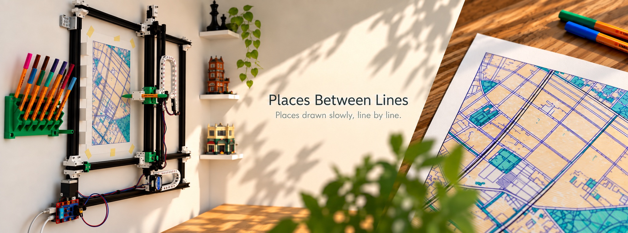
Building a pen plotter
At Places Between Lines, we decided to build our own pen plotter rather than buy an existing one. This gives us the flexibility to add features that are not commonly found in pen plotters. It is also cheaper than buying a top-of-the-line machine—and a lot of fun!
Non-negotiable requirements
- High-quality results
- Reliability
- Fast and smooth operation
Additional features
- Wall-mounted design. This allows us to run multiple large machines in a limited space.
- Wireless control. We want to operate multiple machines conveniently from a single computer.
- Automatic pen changes. These keep the machine busy for longer without human intervention.
Mechanical design
We built the machine’s frame from 2020-type V-slot aluminium extrusions and 3D-printed corner brackets. It has an H-frame design, 80 cm wide and 60 cm tall, with the gantry forming the Y-axis. The gantry’s weight is supported by POM wheels running in the extrusions’ V-slots, so the X-axis motor does not have to fight gravity. Two timing belts inside the aluminium extrusions drive the gantry. A single motor drives both belts through an aluminium rod, allowing the gantry to move quickly and precisely without deflection. The Y-axis uses a similar timing belt, and POM wheels let the tool mount ride along its aluminium extrusion.
The Z-axis, like the other axes, uses a stepper motor. We initially used a 9 g servo, as is common in DIY pen plotters, but soon found that upgrading to a stepper-driven axis was worth the effort. It is faster, more precise, quieter, and lets us separate Z movements cleanly from XY movements. With a 9 g servo, it is hard to know when a movement has finished. Sideways movements can then blend with Z movements, or ink can bleed into the paper if the pen stays in contact with it for too long.
Each axis has a stepper motor with a 4-pin connector and an endstop switch with a 3-pin connector. Wires run through drag chains along the Y- and X-axes to the controller board in the machine’s bottom-left corner.
The panel that holds the paper is also attached to the aluminium extrusions. It adds stiffness to the frame and provides a relatively flat surface at a known distance from the pen.
Pen change
An M4 screw holds the pen inside an adapter. We can quickly swap it for a different colour or replace it when it runs low on ink. Four neodymium magnets attach the adapter to the tool post. To change pens during a plot, the machine runs a sequence of moves that drops the old pen and picks up the new one.
Pen tip alignment
When a pen is mounted in its adapter, we can adjust its position along the Z-axis using a handheld tool. To locate it precisely along the X- and Y-axes, we developed a mechanical pen-tip sensor. It uses probing commands to locate the pen tip and applies that information to subsequent plotting moves.
Pen pressure
This topic deserves a lengthy explanation. Pen pressure caused problems early on, and we did not solve them until we focused on the issue fully.
Problem statement
Pen pressure—the force with which the pen presses against the paper—is an important part of plotting. If it is too low, lines become thinner, then intermittent, and eventually disappear when the pen tip loses contact with the paper. If it is too high, the pen scratches the paper audibly and its tip wears down. The pen holder may also lose its grip, or the Z-axis motor may skip steps because of its limited torque.
Z-axis movements can control pen pressure precisely, but the plotter’s back panel is uneven, causing pressure to vary across the surface. Even with a measured peak-to-valley offset of just 1.2 mm, we saw both excessive pressure at peaks and insufficient pressure in valleys.
We need roughly 0.2–0.3 N of force throughout a 2 mm range of motion. Ideally, that force would be constant and, better yet, adjustable in software.
Idea 1: Use a perfectly flat back panel
We considered acrylic because it appears perfectly flat, but ruled it out because it deforms with temperature changes. Its coefficient of thermal expansion is about three times that of the aluminium in the frame, so the panel could buckle and become less flat than the original ACP panel.
Acrylic was also found to flex too easily, and if a thicker panel were used to mitigate this, it would be quite heavy and expensive.
Idea 2: Use a constant-force spring
Constant-force springs maintain a steady force over a long range of motion. However, they may be difficult to use here because they pull rather than push, and are generally made for much higher forces than we need.
Idea 3: Use a softer spring
A softer spring would still apply more pressure as it compresses, but if it were long and soft enough, the pressure might stay within the desired range over a greater distance.
We 3D-printed many springs with different levels of softness. We found that a spring that is too soft makes the pen’s position difficult to control. The linear bearing has low friction, but the motion becomes jittery if the pen holder is pushed at even a slight angle. The pen may then fail to touch the paper or lift reliably. Precise control of the pen holder’s position is also essential for reliable pen changes.
Idea 3.1: Use rotating linkages instead of a linear guide
Because the linear guide’s friction does not work well with a soft spring, we considered replacing it with linkages. We quickly discarded the idea: it would mix Z and Y movements, and it is hard to imagine a 3D-printed linkage constraining the pen holder as well as a purpose-built hardware component while also reducing friction.
Idea 4: Use gravity
Pen plotters usually lie flat and use the pen’s weight to maintain constant pressure across the plotting area. Ours is wall-mounted, so it needs another way to create pressure. We could still use gravity by transferring the pull of a weight to the Z-axis through a lever. With lever arms of different lengths, we could use a small weight and tune the force by changing it.
One concern is acceleration along the other axes. When the pen holder accelerates up or down along the Y-axis, pen pressure would momentarily decrease or increase. However, the current acceleration limit of 500 mm/s² is only 5% of Earth’s gravity, and the machine is fast enough at this setting.
We never tested this idea because, like the softer-spring approach, it is limited by friction in the linear guide (see Idea 3). The weight and lever would need to produce only 0.2–0.3 N of force—our target pen pressure—and we doubt they could reliably overcome that friction.
Idea 5: Use a load cell and control loop
Other pen plotters have shown that a load cell can measure the force of the pen against the paper. A feedback loop could use that measurement to adjust the Z-position continuously, using either the existing Z-axis motor or another actuator—perhaps a magnetic one—to maintain constant pressure. Essentially, this would be a smart spring, either as a standalone module or integrated with the existing controller hardware.
This would be exciting to try, but the complexity ultimately stopped us from ordering parts. As we considered more problems and possible workarounds, we became more convinced that a much simpler, ideally passive, mechanical solution had to exist.
Idea 6: Bed mapping
3D printers handle uneven work surfaces by measuring height offsets and compensating in software. We revisited this idea whenever a mechanical solution fell through, but never pursued it seriously. Eventually, it became clear that bed mapping was a promising option:
- Pen pressure would remain nearly constant, even if the surface were very uneven.
- Surface offsets need to be measured only once, and can be measured precisely.
- AI makes software changes easy to implement.
We implemented bed mapping in less than a day, and it has worked flawlessly from the start. In hindsight, it was an elegant, robust solution to a problem that had bothered us since the beginning of the project.